Page 12 of 20
Re: Double Trouble

Posted:
Sun Jan 31, 2021 10:38 amby John H
I enjoy your input Gordon. Stop by when you have time.
Re: Double Trouble
Posted:
Sun Jan 31, 2021 11:22 amby ATinkerer
Thank you John,
Not getting out much these days, for quarantine reasons.
Re: Double Trouble
Posted:
Thu Feb 04, 2021 8:36 pmby John H
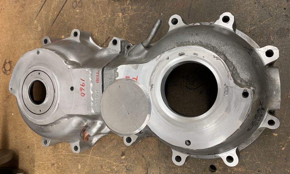
The main bearing races are finished and the disk is ready to be welded to the cases. It will then be bored for the new oil seal.
- IMG_3681.JPG (265.62 KiB) Viewed 13681 times
Re: Double Trouble
Posted:
Thu Feb 04, 2021 10:42 pmby ATinkerer
Pretty work, as usual John.
Gordon
Re: Double Trouble
Posted:
Fri Feb 05, 2021 8:35 pmby John H
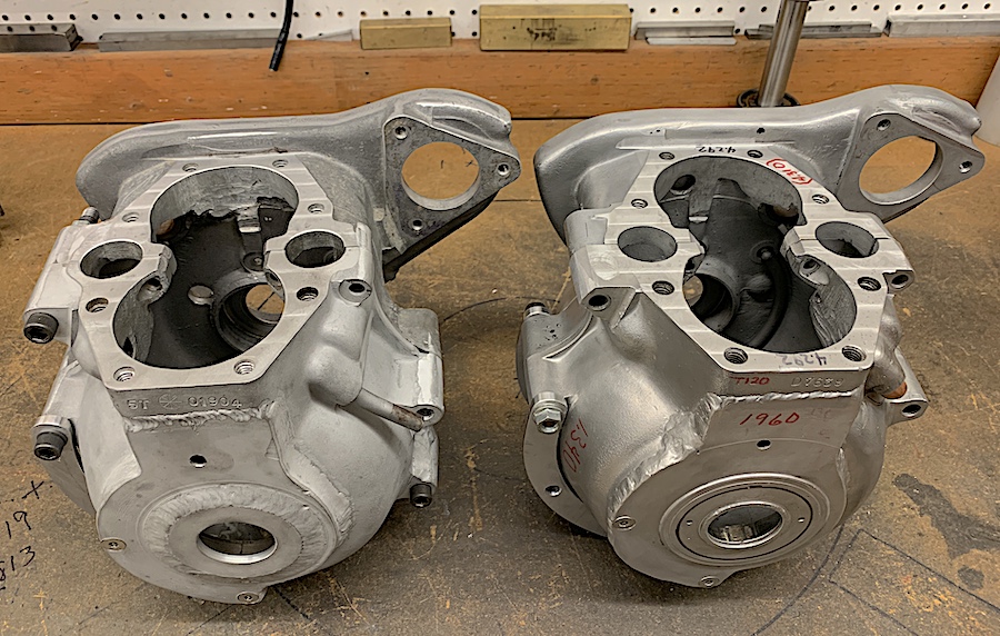
Finished the engine mounting spacer plates making them so they cover the 3 front mounts instead of 3 small spacers.
Welded the plate to the case and bored it for the crank seal. Last thing to resolve is removing the intake cam bushing and taking the timed breather disk out to replace the locating pin. Not sure how this will be done as the pin can't be driven out. If all else fails I'll just remove the disk and put a pcv valve on the breather pipe.
- IMG_3696.JPG (273.1 KiB) Viewed 13675 times
Re: Double Trouble
Posted:
Tue Feb 09, 2021 7:51 pmby John H
The new crankshaft seals arrived today and are too large for the old bore. Old seals were for 1.627 od and the new ones are 1.632 od. So the cases have to be machined again for the .002 interference fit.
Re: Double Trouble
Posted:
Wed Feb 10, 2021 9:48 pmby John H
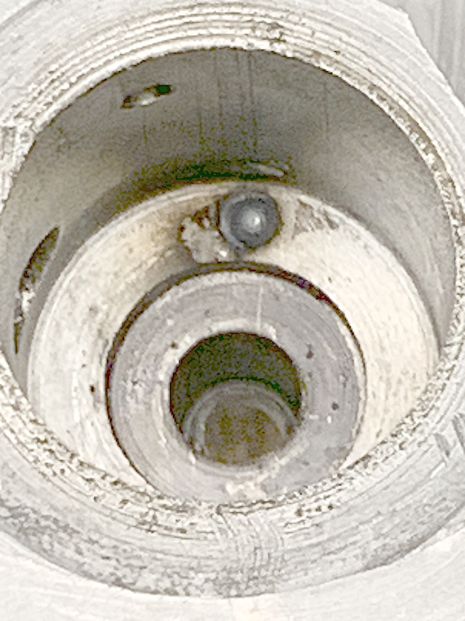
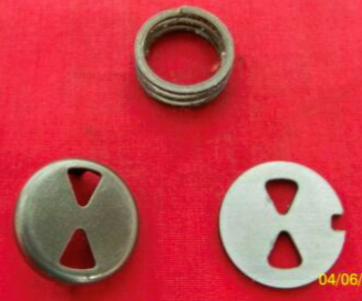
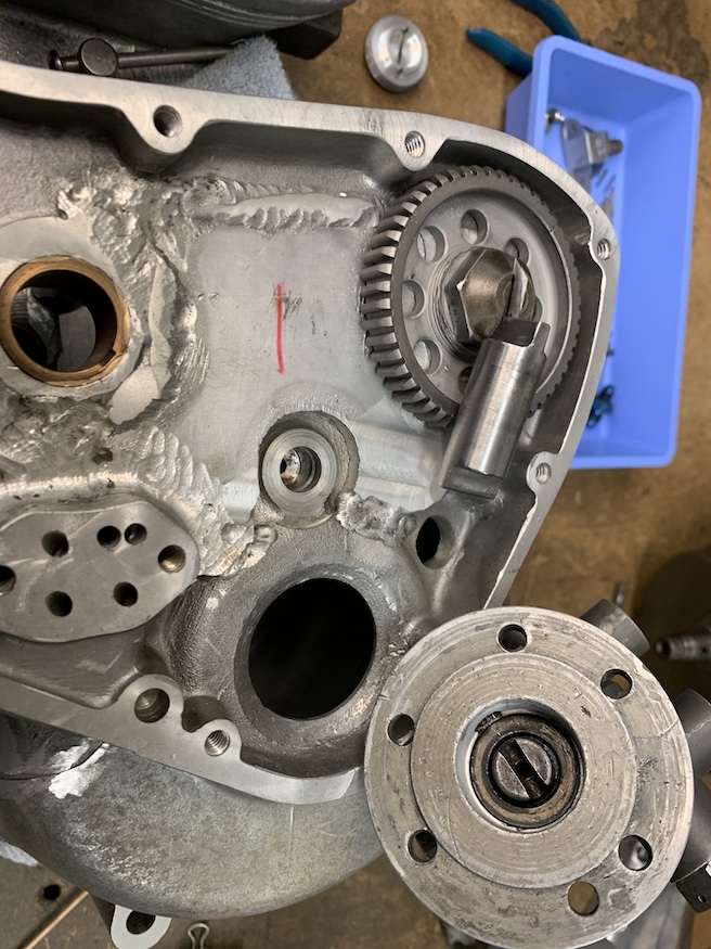
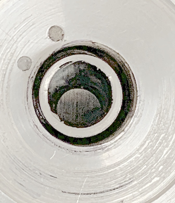
I machined the cases today to fit the new seals correctly. Still scheming on a way to fix the timed breather disk behind the cam bearing, I came up with a fix. Being a blind hole situation, I drilled through the bottom of the breather port to the outside of the case with 3/16" drill bit. The case was then heated to 200º and I used a 3/16" pin punch to drive out the cam bearing and the timing disk. The pin in the bottom of the hole was worn down allowing the timing disk to rotate thus not controlling crankcase pressure. I used an extra long tig torch and welded enough height to the pin to stop the disk ( only .050" thick) from rotating. The 'rotating disk' and spring seen in the second photo is timed off of the end of the cam. The disk and cam bearing was replace and rotated smooth so I welded up the pin punch hole and all is good to go.
- IMG_3728.JPG (168.67 KiB) Viewed 13643 times
- Screen Shot 2021-02-10 at 8.44.31 PM.png (158.67 KiB) Viewed 13643 times
Re: Double Trouble
Posted:
Sat Feb 13, 2021 12:05 amby John H
The fuel pump is driven off the exhaust cam gear which was originally for the tachometer drive. The pump is also slotted so I made a drive shaft to connect the two. It is held in place by a needle bearing in the timing cover so the shaft had to be made from material that can be heart treated.
- IMG_3734.JPG (248.61 KiB) Viewed 13628 times
Re: Double Trouble
Posted:
Mon Feb 15, 2021 8:45 pmby John H
More surprises today. When fitting the timing cover with the new driveshaft it became apparent the location of the needle bearing is off by .040". Don't now how it ever ran this way but it will be bored and sleeved then bored again to be centered on the end of the camshaft. Welding the bearing hub to the cover caused a lot of distortion so while in the mill a light cut was made to true up the mating surface.
Re: Double Trouble
Posted:
Tue Feb 16, 2021 10:36 pmby John H
With all dowels in place the cover was bored to .998" and an aluminum sleeve was turned to .999" od. Next will be to heat the cover to 200º and insert the sleeve. Some welding will be required to give added support to the sleeve. Once this is done the cover will then be bored to fit the needle bearing.
- IMG_3745.JPG (135.48 KiB) Viewed 13567 times
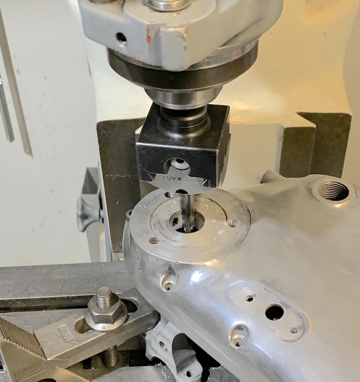
- IMG_3746JPG.JPG (137.21 KiB) Viewed 13567 times